
1. Description
It is a conditional component designed to create a loop that will repeat while the checked condition is true.
This component is present in flow types like:
-
Voice;
-
Chat;
-
Forms;
-
Service.
The block (Fig.1(1)) is used in space to build the Flow. The settings panel for this component opens (Fig.1(2)) when you click on the block.
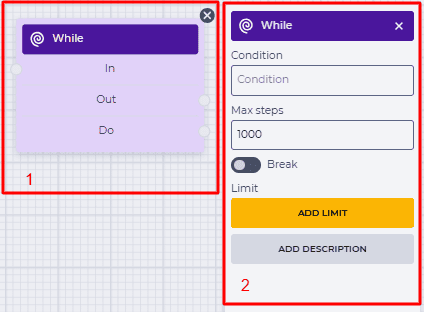
Fig.1. While component
1.1. While block
The block consists of the following elements:
-
The name of the component;
-
In branch — receiving (connecting with the previous block) branch;
-
Out branch — execution of the Flow scheme on this branch occurs if the condition specified in the Condition field is not met or after execution of the Flow scheme on the do branch the number of times entered in the settings. The maximum number of passes is set in the Max steps field. Outgoing branch (connecting to the next block);
-
Do branch — execution of the Flow scheme on this branch occurs when the condition specified in the Expression field is met.
When hovering over the Out, or Do field, a switch appears. The switch allows this component to be connected to a component that already has a connection.
The presence of an 
Changing the switch position removes the outgoing branch of this component.
The 
1.2. While settings panel
It consists of the following elements:
-
Condition;
-
Max steps;
-
Break;
-
Limit;
-
Add description.
1.2.1. Condition
The test condition is entered here.
All variables in Webitel are marked like this — ${ }. The variable name is enclosed in curly braces. The next step is to specify the condition.
For example, it is necessary to check whether the variable out_w is more significant than zero. The field entry will look like this:
${out_w}>0
If the condition is met, the do branch is used.
1.2.2. Max steps
Here, you enter the maximum number of passes on the do branch — the condition entered in the Condition field is met.
It is used to avoid looping of the circuit.
1.2.3. Break
Responsible for the completion of the flow execution.
-

-

1.2.4. Limit
It is intended to determine the maximum number of passes through this component.
The failover branch appears in the edited component when the limit is set 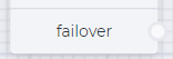
The failover branch will be used if more passes are passed through the component than entered in the Max field.
Clicking on the Add Limit button adds a Max field and a Delete limit button.
The number of possible passes is indicated in the Max field.
Clicking on the Delete limit button removes the limit and returns the Add limit button.
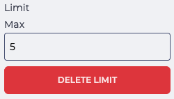
Fig. 2. Setting a limit
1.2.5. Add description
When you click the Add description button, a Description field and a Delete description button will be added.
The Description field is used to add comments to the component.
Clicking the Delete description button removes the description field and brings back the Add description button.
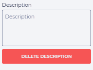
Fig. 3. Add description